Advanced Technologies
Industry-leading NDT equipment and robotic systems for onshore, offshore and subsea asset integrity solutions.
Our Technology Portfolio
Specialized technologies for comprehensive asset integrity — from tank floors to subsea hulls.
SLOFEC® FloorScanner
Tank Inspection
CUI / Pulsed Eddy Current (LYFT)
Corosion Under Insulation
ACFM Eddy Current
Advanced Alternating Current Field Measurement
Magg310 Underwater Robot.
Inspection
FOCUS+ Guided Wave Testing.
Long Range
SLUDGE PROFILING OF OIL TANKS
Sludge Profiler of Crude Oil Tanks.
Robotic Blasting & Surface Prep.
Automated Coating Removal System
MARINE GROWTH PREVEBTION SYSTEM
Keep jetty piles clean, visible and inspection-ready.
INTERGRIID®
Digital Condition-Based Management (DCBM) Solutions
SLOFEC® FloorScanner
Tank Inspection
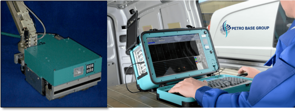
SLOFEC® FloorScanner
he SLOFEC® FloorScanner is an advanced electromagnetic tank floor inspection system that uses Saturated Low Frequency Eddy Current technology to detect corrosion and wall loss in storage tank floors — even through coatings.
How It Works
The system uses eddy current technique with an array of sensors fixed in a carrier driven along the surface. It detects surface cracks even under non-conductive coatings. The scanner employs 8-sensor arrays covering both weld zones and heat-affected zones, with spring-loaded holders that follow weld contours for precise detection
Key Applications
- Tank Floor Mappind
CUI / Pulsed Eddy Current (LYFT)
Corosion Under Insulation
CUI / Pulsed Eddy Current (LYFT)
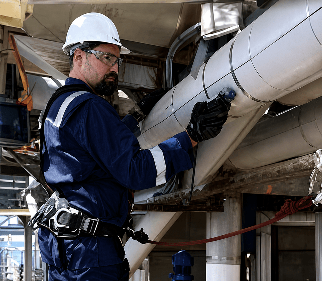
Corrosion Under Insulation (CUI) remains one of the thorniest asset integrity problems in the industry. Petro-Base addresses this with high-performance Pulsed Eddy Current (PEC) LYFT technology — detecting wall loss through metal up to 100mm and insulation up to 300mm.
How It Works
PEC technology sends pulsed electromagnetic fields through insulation and weather jackets to measure remaining wall thickness. The LYFT system can penetrate Aluminium, Stainless Steel and Galvanized weather jackets. The PEC ARRAY probe displays C-scan with A-scan at scanning speeds up to 6× faster than conventional methods.
Key Applications
- Insulated piping inspection
- Pressure vessel assessment
- Petrochemical plants
- Refinery infrastructure Offshore topside facilities
ACFM Eddy Current
Advanced Alternating Current Field Measurement
ACFM Eddy Current
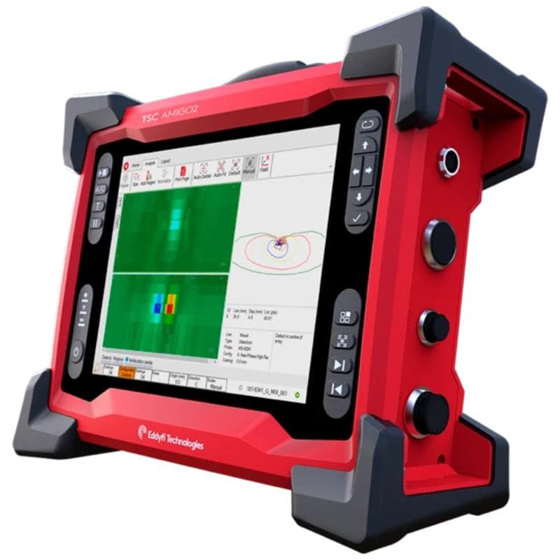
Our ACFM (Alternating Current Field Measurement) system provides reliable, repeatable crack detection on any type of welding with maximum coating of 5mm — no surface cleaning required. Built-in 5MP camera captures on-site documentation.
How It Works
ACFM works by introducing an alternating current into the surface of the component being inspected. When a crack is present, the current flow is disturbed, and the resulting changes in the magnetic field above the surface are detected by sensors. This allows accurate measurement of crack length and depth without removing coatings.
Key Applications
- Weld inspection
- Painted and coated structures
- Cranes and towers
- Refinery piping and vessels
- Bridges and infrastructure
- Topside onshore/offshore structures
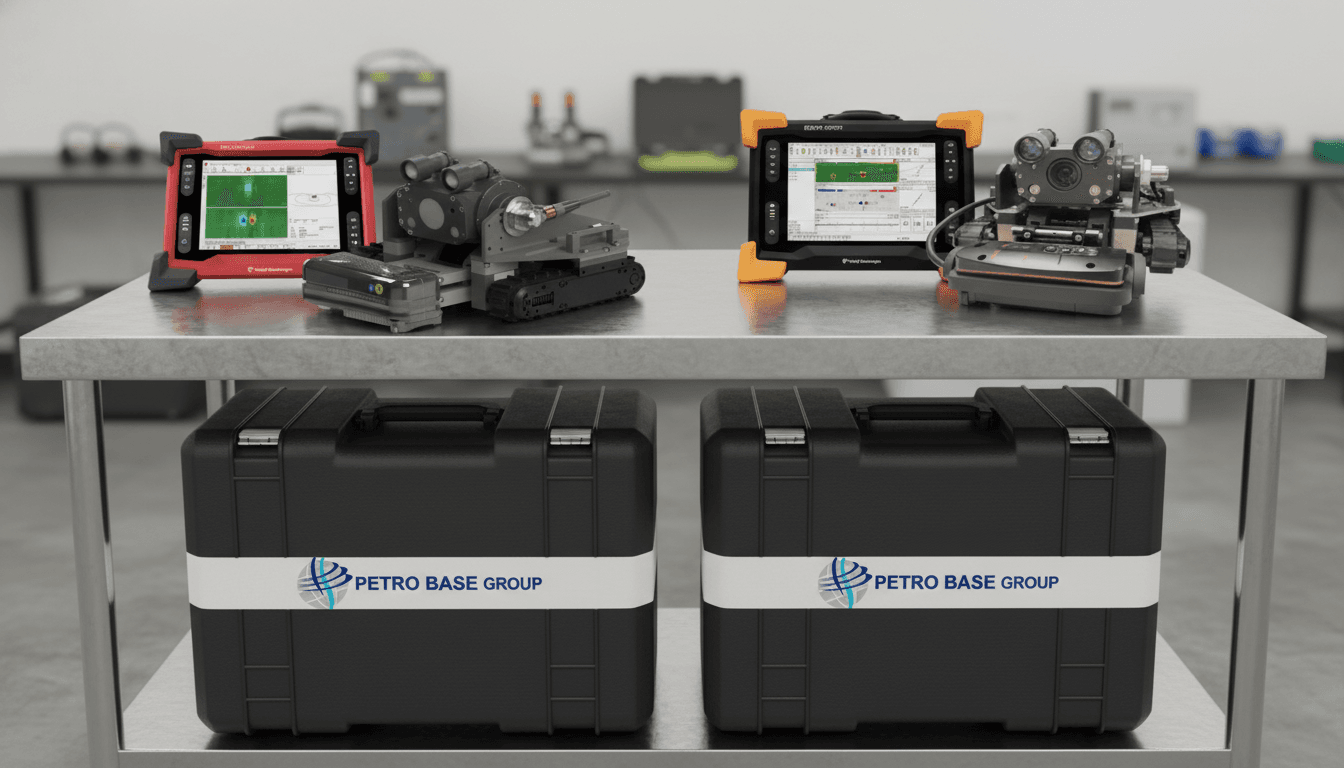
Magg310 Underwater Robot.
Inspection
Magg310 Underwater Robot.
The Magg310 is a submersible robotic delivery system designed for underwater and topside deployment of NDT sensors. Its modular platform features tool-free mounting, allowing multiple inspection modalities depending on requirements, conditions and environment.
How It Works
The Magg310 uses magnetic crawling technology to adhere to steel surfaces above and below water. Multiple NDT sensor modules can be mounted without tools, enabling rapid reconfiguration between UT, PAUT/TOFD, ACFM, ECA/PECA, and Remote Visual Inspection modalities. The system is controlled via a 100m tether with full HD camera feed.
Technical Specifications
Operation Distance
100 m (tether)
Depth Rating 60 m
60 m
Crawling Speed
3.6 m/min
Camera
Full HD, 160° pan, 10× optical zoom
Modalities
UT, PAUT/TOFD, ECA/PECA, ACFM, RVI
Key Applications
- FPSO hull inspections
- UWILD / Class / Flag inspections
- Underwater hull cleaning
- CP anode surveys
- Large diameter pipeline internal inspection
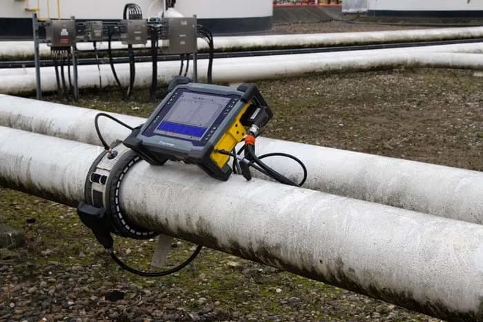
FOCUS+ Guided Wave Testing.
Long Range
FOCUS+ Guided Wave Testing.
The FOCUS+ unit uses guided wave technology to screen long lengths of pipe for anomalies. Unlike conventional UT which tests only the area beneath the transducer, guided waves can inspect entire pipe segments rapidly — then focus in on problem areas with precision.
How It Works
The computer-controlled, battery-operated unit uses an integrated pump for collar inflation around the pipe. Guided waves propagate along the pipe wall, reflecting from corrosion, erosion or other anomalies. The FOCUS+ software automatically performs most setup functions and enables one-click focusing on localized areas of interest.
Technical Specifications
Power
Battery operated
Collar Inflation
Integrated pump
Control
Computer-controlled
Focus Mode
One-click localized focusing
Software
User-friendly auto-setup
Key Applications
- Long-range pipe screening
- Corrosion detection under supports
- Road crossing pipe inspection
- Insulated pipe assessment
- Offshore riser inspection
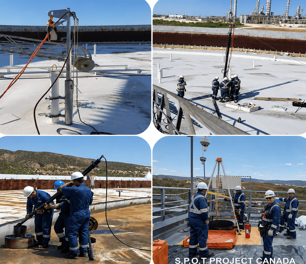
SLUDGE PROFILING OF OIL TANKS
Sludge Profiler of Crude Oil Tanks.
SLUDGE PROFILING OF OIL TANKS
The S.P.O.T system uses patented sonar technology to scan sludge in the base of crude oil storage tanks, producing a complete 3D contour model of the sludge/oil interface. Over 400 surveys conducted worldwide with 99.9% coverage accuracy.
How It Works
A nitrogen-purged, ATEX-certified and intrinsically safe transducer robotically rotates through 360°, sweeping the sludge surface with up to 240,000 soundings. The sonar beam has a range of approximately 30 meters. Processed acoustic echoes produce an accurate profile of the sludge/oil interface, displayed as plan view and 3D models.
Technical Specifications
Rotation
360° robotic sweep
Soundings 0
Up to 240,00
Sonar Range
~30 meters
Safety Certification
ATEX Certified, Nitrogen Purged
Access Requirement
Min. 10 mm / 4" roof leg sleeve
Outpu
t 3D contour model, plan view
Key Applications
- Crude oil tank sludge volume quantification
- Storage capacity assessment
- Floating roof landing safety evaluation
- De-sludging planning and scheduling
- Mixer pattern monitoring
- Sludge sampling location identification
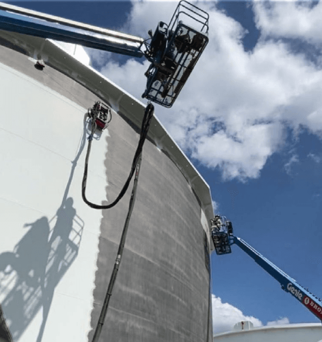
Robotic Blasting & Surface Prep.
Automated Coating Removal System
Robotic Blasting & Surface Prep.
Our robotic blasting system provides environmentally friendly, zero-discharge coating removal and surface preparation. The fully contained system uses vacuum and magnets to adhere to any steel surface orientation — vertical, horizontal, or inverted.
How It Works
The robot utilizes ultra-high pressure water jetting (up to 55,000 PSI) to remove coatings while maintaining 100% containment of water, paint and corrosion debris. Magnetic and vacuum adhesion allows the unit to operate on any surface orientation. Wireless remote control enables safe operation from a distance.
Technical Specifications
Productivity
~500 sqft per 12-hr shift (= 8 sandblasters)
Cutting Swath
18"
Max Speed
30 ft/min
Weight
140 lbs
Max Pressure
55,000 PSI
Control
Wireless remote
Containment
100% — water, paint, corrosion
Key Applications
- Storage tank surface preparation
- Vessel coating removal
- Pipeline maintenance
- Offshore structure refurbishment
- Industrial painting preparation
MARINE GROWTH PREVEBTION SYSTEM
Keep jetty piles clean, visible and inspection-ready.
MARINE GROWTH PREVEBTION SYSTEM
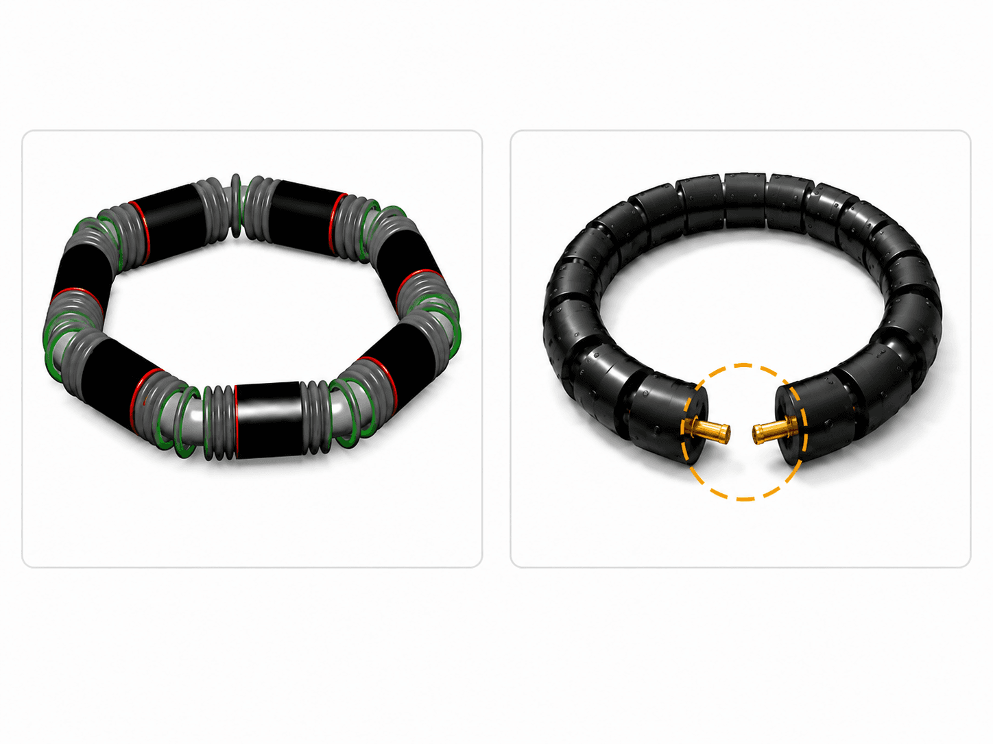
The Marine Growth Prevention System (MGP) is an ocean-powered mechanical solution that prevents marine growth from building up on jetty piles.
How It Works
The Marine Growth Preventer (MGP) is an ocean-powered mechanical system designed to prevent marine organisms from settling and building up on jetty piles. It uses the natural movement of waves and tides rather than electricity or chemicals. 1. Wave and Tide Motion. The movement of the ocean causes the MGP device to move, travel and rotate around the jetty pile. The system essentially uses the energy already available in the marine environment to operate itself. 2. Mechanical Cleaning Action As the MGP moves around the pile, its rollers and brushes mechanically remove marine settlement from the pile surface before it becomes firmly established. 3. No Electricity or Chemicals The system does not depend on electrical power or chemical treatment. Its operation is powered by ocean energy alone, making it a mechanical and environmentally considerate approach to marine-growth prevention. 4. Keeps the Pile Inspection-Ready By continuously preventing significant marine growth in the protected zone, the pile remains cleaner, more visible and easier to inspect. This helps inspectors see the underlying pile surface and identify potential problems more effectively. In Simple Terms Ocean waves & tides → Move MGP → Rollers & brushes act on pile → Marine settlement is removed/prevented → Pile stays cleaner → Easier inspection The document describes the overall concept as: “The sea provides the movement. MGP provides the mechanical prevention.” Key Benefits Zero electricity Zero chemicals No scheduled maintenance Ocean-powered operation Mechanical prevention of marine growth Cleaner protected zone Improved visibility of jetty piles Easier inspection Designed for jetty splash/wave zones
Key Applications
- Jetty & Pier Piles
- Refinery & LNG Terminals
- Port & Terminal Facilities
- Steel Piles
- Concrete Piles
- Marine Asset Maintenance
INTERGRIID®
Digital Condition-Based Management (DCBM) Solutions
INTERGRIID®
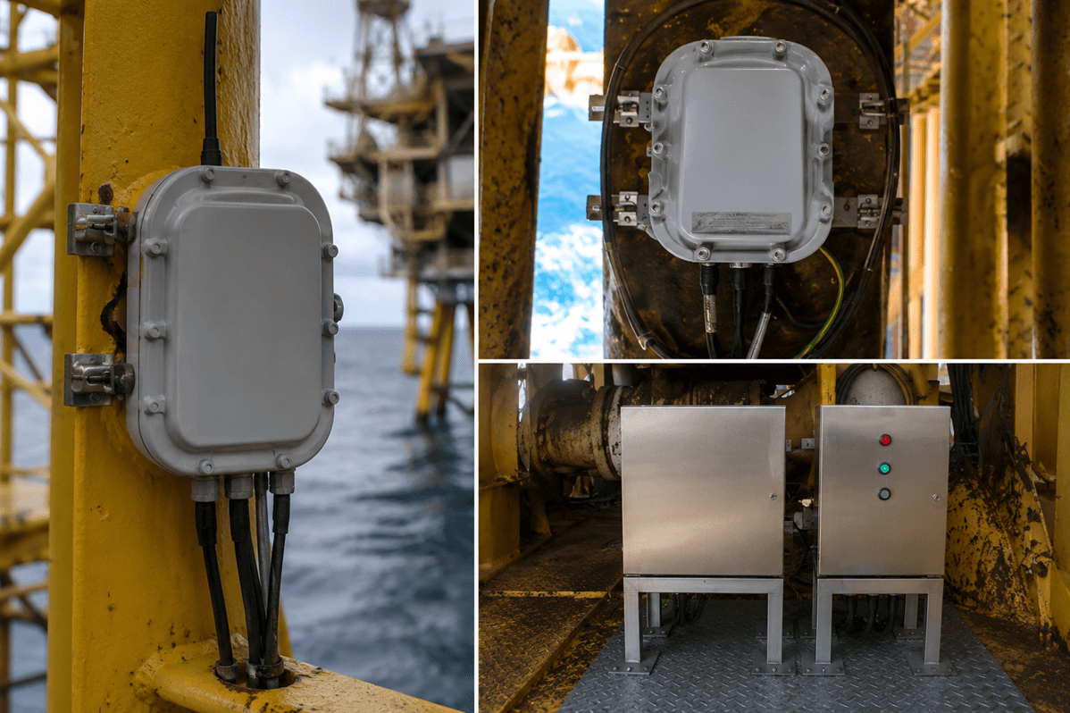
INTERGRIID is a Digital Condition-Based Management (DCBM) platform for offshore structural integrity management. It combines measurement, monitoring, engineering models, and risk analysis to support evidence-based decisions for offshore assets.
How It Works
INTERGRIID works by transforming offshore asset integrity management from periodic, assumption-based inspections into a continuous, evidence-based monitoring system. Instead of relying solely on engineering calculations, it continuously measures how a platform actually behaves and uses that information to guide inspection, maintenance, and life-extension decisions. Overall Workflow 1. Measure The first step is to measure the platform's actual structural behavior offshore using sensors. The system collects data such as Accelerometer readings Structural strain Meteocean (environmental) conditions The goal is to understand how the structure behaves under real operating conditions rather than relying only on theoretical models. 2. Compare. The measured behavior is then compared against the engineering design model. Specifically, the system compares: Measured structural response Design models created in tools such as SACS and SESAM This determines whether the platform is behaving as engineers expected. 3. Rank INTERGRIID ranks every offshore asset according to its measured risk. Instead of inspecting all platforms on a fixed schedule, assets with the greatest evidenced risk receive priority attention. 4. Act Finally, the measured evidence is used to drive operational decisions, including: Risk-Based Inspection (RBI) Inspection planning Maintenance Asset life-extension decisions The presentation emphasizes that actions are based on measured evidence rather than conservative assumptions. Three Core Capabilities The presentation explains that the platform is built around three complementary capabilities. IG-Insight (Structural Health Check) A short-term measurement campaign that: Measures dynamic structural condition Verifies engineering models Supports pre-life-extension assessments Performs post-event inspections Its purpose is to answer: "What does the platform look like today?" IG-Monitor (Structural Health Monitoring) This component installs permanent sensors on the offshore platform. It continuously: Monitors structural trends Detects changes in stiffness Detects changes in structural mass Detects abnormal dynamic responses Builds a live digital twin Its purpose is to answer: "Where is the platform heading?" IG-Assure (Dynamic Risk Assessment) The measured structural behaviour is converted into engineering risk metrics. It calculates: Structural Reliability Index (SRI) Probability of Failure (PoF) Dynamic Risk-Based Inspection recommendations Its purpose is to answer: "What does the measured risk mean?" The Technical Principle A central idea in the presentation is that every offshore platform behaves like a mass–stiffness system. Changes in either the platform's stiffness or mass alter its natural frequency, making natural frequency an indicator of structural health. The presentation notes that trends in natural frequency can reveal changes caused by factors such as marine growth, scour, soil changes, corrosion, or section loss. The system therefore monitors structural behaviour rather than waiting for visible damage. Model vs Reality Engineering Model Predicts how the platform should behave using geometry, soil, loading, and mass assumptions. Measured Monitoring Shows how the platform is actually behaving under real environmental and operational conditions. If the measured and modelled behaviour align, engineers gain confidence in continued safe operation. If they diverge, the system recommends investigation, model updates, Risk-Based Inspection (RBI) updates, and targeted inspections. End-to-End Process The technology's complete process, as described in the presentation, can be summarized as: Install sensors or use existing inspection data. Collect real-time structural measurements. Analyse structural behaviour. Compare measured behaviour with engineering models. Detect structural changes and anomalies. Calculate reliability and probability of failure. Rank assets by measured risk. Update inspection schedules and maintenance plans. Support life-extension decisions with evidence rather than assumptions.
Key Applications
- Structural Health Monitoring (SHM)
- Structural Health Check (SHC)
- Digital Twin Validation
- Risk-Based Inspection (RBI)
- Predictive Maintenance
- Asset Life Extension (ALE)
- Reliability and Risk Assessment
- Portfolio Integrity Management
Ready to optimize your infrastructure?
Consult with our senior engineers today for a comprehensive evaluation of your project requirements.